
 The International Electrotechnical Commission has published a new Technical Specification called IEC 60079-32-1: “Explosive atmospheres - Part 32-1: Electrostatic hazards - Guidance”. This Technical Specification is a guidance document which is the latest addition to the IEC series of 60079 “Explosive Atmospheres” standards that are designed to limit fires and explosions caused by electrical malfunctions within hazardous areas.
The 168 page document is the first of two documents to be published by the under IEC the “60079-32” designation and is intended to aid the designers and users of process equipment minimise the risk of incendive electrostatic discharges within potentially explosive atmospheres. It covers a broad range of process scenarios that can lead to the generation of electrostatic charges, provides examples of what measures can be taken to reduce charge generation and accumulation and outlines how process equipment should be grounded and bonded.
The second part, IEC 60079-32-2, is entitled “Electrostatics hazards – Tests” and outlines test methods to determine factors like surface resistance, earth leakage resistance, powder resistivity, liquid conductivity, capacitance and the incendivity of electrostatic discharges.
The stated objective of IEC 60079-32-1 is to provide:
“… the best available accepted state of the art guidance for the avoidance of hazards due to static electricity”.
To date guidance documents that address the ignition hazards of static electricity have either been published by national institutions like the NFPA or pan-European organisations like CENELEC. IEC 60079-32-1 has been collectively developed by a large number of technical committees from IEC member countries, making this document a truly global collaboration. It also builds on the work of national and regional guidance documents addressing electrostatic hazards, including CENELEC/TR: 50404, NFPA 77, BS 5958, TRBS 2153:2009 and JNIOSH TR42.
Although the Technical Specification can be purchased from the IEC’s webstore, it will be the responsibility of national standards institutes like the ANSI in the U.S., BSI in the U.K. and DIN in Germany to administer the circulation of the document in their respective national territories. The ANSI has the document available for purchase from its website. Cenelec has withdrawn CLC/TR: 50404 and replaced it with CLC/TR 60079-32-1.
Overview of the Technical Specification:
The Technical Specification is sub-divided into what are termed “clauses” that highlight the electrostatic hazards associated with various categories of materials, the hazards associated with people, including physiological shocks, and what grounding and bonding measures should be put in to practice. The clauses are presented as:
1) The handling of solids.
2) The storage and handling of liquids.
3) The handling of gases and vapours.
4) The storage and handling of powders.
5) The storage and handling of explosives.
6) Electrostatic problems caused by people.
7) Avoidance of electrostatic shock.
8) Earthing and bonding of plant and machinery.
There are also several Annexes that provide informative material, examples of which include a description of the various types of electrostatic discharges, the types of electrostatic discharges that can be expected from processes carried out within potentially flammable and combustible atmospheres and the provision of an illustrated flowchart for assessing electrostatic hazards.
Owing to the fact that the document is 168 pages long, it would be impossible to provide a comprehensive overview of the guidance contained in the document in just a few pages. However, it would be worth touching on guidance related to the grounding and bonding of specific processes that utilise portable equipment at risk of static charge accumulation.
The design and monitoring of grounding systems: This section addresses the design and monitoring of systems dedicated to grounding permanent and portable plant equipment. Permanently installed plant equipment like reactors and pumps will most likely be grounded via the electrical grounding system for the plant. Electrical fault paths (and lightning protection paths) are more than adequate to dissipate electrostatic charge to ground.
For portable conductive equipment this section recommends that temporary connections using bolts or “pressure-type” clamps are capable of penetrating protective coatings, rust or product deposits that are typically present on the surface of such equipment, e.g. metal drums. It states that pressure type clamps should be capable of establishing a connection resistance of less than 10 Ohms to the base metal of the conductive equipment.
Systems designed to monitor the resistance between equipment at risk of charge accumulation and earth (designated grounding points) should not only be capable of monitoring the resistance in the grounding circuit, but should also be capable of drawing attention to any changes in resistance. This is to ensure that malfunctions in the grounding circuit are detected as early as possible so that inspections and necessary repairs are made in good time.
Given that metal grounding circuits should not display a resistance above 10 ohms it would be prudent to specify grounding systems that are capable of identifying changes in resistance and alerting personnel as soon as 10 ohms in the ground path is exceeded.
Type C FIBC:
This section describes which hazardous zones the four bag types (A,B,C,D) are suitable for use in. The “zones” are based on the IEC method of hazardous area zoning classification which have been adopted in ATEX legislated countries, the U.S. NEC 505 & 506 and the Canadian CEC. It also specifies the types of liners (L1, L2, L3) and FIBC bag type combinations that may or may not be used in hazardous areas. This section heavily references IEC 61340-4-4: “Electrostatics – Part 4-4: Standard test methods for specific applications – Electrostatic classification of flexible intermediate bulk containers (FIBC)” which specifies the construction, testing and labelling criteria for Type A,B,C,D FIBC bags.
Under the requirements of this standard Type C bags must be grounded and for those manufacturing or using Type C bags the resistance from any part of the bag to a groundable point on the bag shall be less than 10 Meg-ohm. This means that the conductive fabric or filaments that make up the grounding path for electrostatic charges should not have a resistance of more than 10 Meg-ohm to the bag’s grounding point. This is a change from CLC/TR: 50404 which recommended a maximum resistance of 100 Meg-ohm.
The safest method of grounding Type C bags is to ensure the resistance through the bag is less than the benchmark value set by the standard(s) the site wishes to comply with. If a grounding system is to be specified, it is important to ensure the system tests the full range of permitted resistance.
The specified resistance range for an IEC 61340-4-4 compliant bag will be any value under 10 Meg-ohm. This section states that if Type D bags are used they do not need to be grounded, but conductive objects within the vicinity of the bag must be grounded.
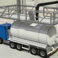
Road Tankers:
The precautionary guidance regarding the grounding of road tankers reflects the stated goal of the technical specification providing the latest state of the art guidance. Section 7.3.2.2.3, part C, states that the “earth cable” earthing the tanker should be part of a static grounding system that continuously monitors the resistance between the road tanker and the designated grounding point located on the loading gantry. It states that the grounding system should be interlocked with the transfer system to shut down the product transfer operation if this resistance exceeds 10 ohms.
It also states that the grounding system should be capable of recognising when it is not connected to the chassis/tank of the road tanker. This ensures that situations where the tank of the road tanker is not connected to the grounding system, for example, where an operator could connect the clamp to an isolated metal mud-guard or wheel-nut, will not result in a permissive condition for the transfer operation, thereby eliminating the risk of electrostatic charging of the road tanker.
Vacuum trucks:
The precautionary measures for the grounding of vacuum trucks state that the truck should be connected to a “designated” site earth before proceeding with the transfer operation. A “designated” site earth is a grounding point that has been verified as having a low resistance connection to “true earth” by suitably qualified engineers. These points are usually identified by tags or labels.
The guidance states that wherever a designated grounding point is not provided and portable ground rounds are permitted for use, or there is doubt regarding the quality of the site designated grounding point, the integrity of that grounding point should be verified prior to the transfer operation. This means that there should be a way of ensuring that the grounding point is actually connected to true earth in order to ensure the charges generated by the transfer operation do not accumulate on the truck or the hoses connected to the truck. This can be achieved via a truck mounted ground verification system or by engineers with ground testing meters. The resistance between the verified grounding point and the vacuum truck should not exceed 10 ohms and it is recommended that this resistance is verified by a truck mounted grounding system which will automatically indicate this to the driver or be verified with an ohmmeter (which should be used by a suitably competent electrical person).
This section also states that hoses used in the vacuuming operation should be compliant with the section covering hoses and hose assemblies. Table 18 in section “7.7.3.4 Properties and usage of ISO 8031 hose assembly grades”, describes the types of hoses that can be used for materials with varying electrical properties.
If non-metallic connections are used to ground the truck up to 1 Meg ohm resistance between the truck and the grounding point is permitted. It should be advised that if a 1 Meg ohm limit is being adopted that the grounding point to which the truck is connected has a verified low connection resistance to true earth, of not more than a few ohms. If a 1 Meg ohm limit is adopted for powder transfers it would be advisable to estimate the charging current generated by the vacuuming operation as very high charging rates are common place with truck vacuumed non-conductive powders.
Personnel grounding, flooring and footwear:
Clause 11 provides guidance on minimising the risk of static electricity accumulating on people and describes various scenarios that can generate electrostatic charges on people. It also describes what methods can be adopted to dissipate charge off people, ranging from guidance on flooring, footwear and additional accessories that can be used to ground personnel working in zoned atmospheres.
Conclusion:
Technical Specification IEC 60079-32-1 is probably the most comprehensive guidance produced on avoiding the hazards of static electricity to date and with the content being developed and approved by a wide cohort of IEC national technical committees, represents a cohesive global approach to controlling electrostatic hazards in the workplace. This article provides a limited overview of the guidance contained in the document. More information regarding the material, processes and equipment that can be susceptible electrostatic discharges, how charging can be minimised and what additional grounding and bonding practices can be put into action are described throughout the different clauses.
