Editorial

GSME and HOTSPOT detector Early detection of explosions + fires


3A17D1AF-D701-462A-B953-8E3683156ADD.jpeg

With the GSME and HOTSPOT detectors from REMBE, an artificial intelligence has been created that detects fire and explosion events at an early stage. The GSME detector is an artificial nose, "trained" for pyrolysis - popularly known as smoldering gases, while the HOTSPOT detector represents an artificial eye that already detects surface temperature changes of 1 ° C.

REMBE´s HOTSPOT X20 measures surface temperatures using an intelligent evaluation system, which divides the field of view into detection zones. A separate temperature threshold value can be set for each individual zone in order to tailor the detection to the process as far as possible. The HOTSPOT X20 can even identify small temperature increases (1°C) and enables to warn the operator of a fire or glowing embers at extremely early stages. The HOTSPOT X20 can also be used in explosion atmosphere up to zone 20 and under high dust loads and monitors a temperature range in the standard version of 0-200°C (higher temperatures possible, but typically not required).

Mainly hydrocarbon compounds are released when many substances thermally decompose. If there is incomplete burning without a flame and a low oxygen supply, carbon monoxide is created as well. The GSME X20 pyrolysis gas detector, for instance, has been designed for detecting these gases, even as they develop. Alongside carbon monoxide and hydrocarbon compounds, nitrogen oxide and hydrogen compounds (CO, HC, H2 and NOx) are also monitored. With the aid of an intelligent evaluation algorithm, a process behaviour can be ideally mapped and normal off-gasing be adopted. If a concentration increases above the usual level, the GSME X20 immediately triggers an alarm. The detectoris also suitable for explosion atmospheres up to zone 20, monitors concentration ranges from 0-100ppm.

When the location and mounting position are ideally designed in an explosion protection concept, HOTSPOT X20 and GSME X20 allow explosions and fires to be prevented through early detection.

CF5B0825-B432-4CD6-AAF3-6903DAA8FD57.jpeg

Fig1: GSME und HOTSPOT detector

About REMBE – the REMBE Alliance introduces itself

Most people associate REMBE with REMBE GmbH Safety+Control, the specialist for explosion safety and explosion venting worldwide. The company offers customers cross-industry safety concepts for plants and equipment. All products are manufactured in Germany and meet the requirements of national and international regulations. REMBE customers include market leaders in various industries, including the food, timber, chemical and pharmaceutical industries.

The company’s engineering expertise is based on almost 50years of application and project experience. As an independent, owner-managed family business, REMBE combines expertise with the highest quality standards and is involved in various specialist committees worldwide. Short coordination paths allow for quick reactions and customer-specific solutions for all applications, from standard products to high-tech special designs.

In addition to REMBE GmbH Safety+Control(www.rembe.de) with approx. 340 employees worldwide, headquartered in Brilon (Hochsauerland, Germany), and numerous subsidiaries worldwide (Italy, Finland, Brazil, USA, China, Dubai, Singapore, South Africa, Japan), four other companies operate under the REMBE umbrella brand:

• REMBE Research+TechnologyCenter GmbH (www.rembe-rtc.de)
• REMBE Advanced Services+Solutions GmbH (www.rembe-services.de)
• REMBE Kersting GmbH (www.rembe-kersting.de)
• REMBE FibreForce GmbH (www.argusline.de)

This article was Also featured in the November/December issue below 
 

Modular Design for Maximum Flexibility


The modular platforms of the HMI portfolio from Pepperl+Fuchs offer individual solutions for applications ranging from non-hazardous areas to Zone 1.


Modular design of VisuNet FLX


The VisuNet GXP and VisuNet FLX HMI device families enable maximum flexibility for use in the process industry. The modular design allows HMI systems to be configured to meet precise individual needs, providing extremely quick, simple service options in the field. This means that a comprehensive range of technologies, installation options, and peripherals is available for customers. Each HMI system consists of at least one computer unit and one display unit, each of which can be individually configured. The operator workstations from Pepperl+Fuchs are designed and certified for use in ATEX/IECEx Zone 1/21, Zone 2/22, and Div 1 applications. In addition, all products can be used in non-hazardous areas.

The VisuNet RM Shell 5 firmware developed by Pepperl+Fuchs for VisuNet thin clients is based on Windows 10 IOT 2019 LTSC and offers a simple way to make individual adjustments. The highest safety standards and flexible configuration options allow connection to numerous virtualized and conventional process control systems.


End-to-end thin client portfolio up to Zone 1/21


The product range is rounded off by rugged box thin clients for use in control rooms and switch cabinets. In addition, mobile tablet thin clients from Pepperl+Fuchs ensure a complete portfolio for virtualized and conventional process control systems. With the VisuNet Control Center software, the thin clients can be managed seamlessly and centrally — from Zone 1 to the control room.

ATEX Fans for Petrochemical Explosion Protection

Petrochemicals are chemicals obtained from refining petroleum, crude oil and natural gas, the primary and raw material sources that enable numerous aspects of modern daily life.Several high-tech separation processes are undertaken in petrochemical plants to convert these raw materials into chemical products such as propylene, xylene, methanol and ethylene. The chemicals are then used to produce everyday products such as plastics, cosmetics, tyres, resins, rubbers, adhesives, and even embalming substances. 

During these high temperature and intensive processes of separation the exhaust streams produce potentially hazardous and corrosive chemical and gas residues. It is crucial that exhaust systems are of the highest corrosion proof quality to ensure safe operation. 

Industrial exhaust fans suitable for this industry are designed for corrosion protection, explosion protection and protection against other elements such as heat, moisture, and salty air. Explosion proof ATEX exhaust fans safely remove and transport the hazardous gases away from personnel and prevent these gases from mixing with other elements to avoid explosions.

What is ATEX 

ATEX stands for atmospheres explosible and refers to an area where there is a potential for an explosion if there is the presence of combustible dust or gases. The potential for the explosion is separated by what is known as gas and dust zones. The more likely an explosion the lower the number related to the zone. For example, zone 0 gas area classification means that an explosion potential is continuously present, zone 2 would mean the explosion potential may occur abnormally and with zone 1 it would occasionally be present. This dictates the type or equipment and the protection rating required to ensure continual safety. The same idea is in place for combustible dusts with zone 20, 21 and 22.

Choosing a Suitable Petrochemical Exhaust Fan

304 stainless steel ATEX fans are the ideal choice due to their ability to handle the extreme temperatures of the fracking process whilst also resisting any corrosive gases that may destroy internal or whole fan components.

304 stainless steel fans are available in two constructions. Either only the internal components are manufactured using stainless steel, if it is only these parts that will be present in the corrosive air, or alternatively, if the entire fan is situated in a corrosive environment and is at risk of rusting as a result, then the entire outer casing and internal components can be manufactured from corrosion resistant materials while still having explosion protection up to zone 1 gases.

ATEX Temperature Classes in Petrochemical

There’s a huge number of processes involved in petrochemical production. The distillation of crude oil which contains a mixture of hundreds of hydrocarbons involves heating in a furnace and the resulting mixture is fed as a vapour into a distillation tower. The chemicals produced have different temperatures that separate them during the fractional distillation stage creating a temperature gradient in the tower <350°C to 25°C. Following the distillation step, cracking is the main process that breaks these mixtures down into hydrocarbons by means of high temperatures and pressure. Hydrocarbons are generally flammable, so its compulsory that ATEX fans are used. Wherever air is contaminated with flammable substances then there is a need for protection.

Industrial fans are temperature rated to ensure that they’re not used in an environment that would exceed the highest acceptable surface temperature on the fan motors surface. If the temperature exceeds this level, ignition of either the gas or dust is possible. This is a required indication that the customer should communicate before any industrial fan selection for an explosive environment. Temperature charts are useful in determining the correct T class based on chemicals in the air stream. For example, Hydrogen is a IIC Gas group with a T temp class making it one of the hottest, most dangerous gases. 

Learn more at www.axair-fans.co.uk


Explosion prevention in new spheres

The topic of “explosion safety” is omnipresent for plant operators and OEM´s when it comes to handling or transporting combustible dusts. Despite the widespread assumption that an increased risk of explosion only exists for gases, enormous forces can also be released by explosive dust- / air mixtures.

To help minimise the risk of explosions when handing combustible dusts, it is important to understand the requirements for an explosion and the respective dust safety characteristics, which are described below. The following picture shows the fire triangle and the explosion pentagon which must be taken into account.

The following conditions must exist for an explosion to occur within a production facility or machine:

Graphic_Explosion_pentagon_web.png

Fig. 1: Explosion pentagon

If any one of the aforementioned prerequisites is eliminated, explosion prevention has intrinsically been practised. However, if this is not possible at all times and in all operating states, explosion hazards will still be present. In this case, it is necessary to divide any potentially explosive atmospheres into zones and systematically apply safety measures.

Drying processes in particular are used in many industries to produce material, for easier storage, more efficient transport and a longer shelf life. However, the combination of moisture extraction and high temperatures creates an increased risk of both, fires and explosions.

If fires and/or explosions occur in drying plants, which are usually very large, the situation is not only extremely dangerous for the machines and the business, but especially for the employees on site.

Operators of spray dryers must combat a particular type of ignition source – namely smouldering nests that can lead to spontaneous combustion if the material undergoes excessive caking. Caking occurs due to sub-optimal drying of the material and its initially high moisture content. The caked material is then insulated against the surrounding air by a build-up of moist material. The high temperatures ensure that the caked material is continuously heated until a biological reaction takes place involving protein, carbohydrate and water – known as the Maillard reaction. The Maillard reaction generates additional heat that cannot be dissipated due to the insulating layer of caked material. This process continues to accelerate until spontaneous combustion finally occurs.

Caking of this kind can build up both on the nozzles and the inner wall of the spray dryers. If the nozzle malfunctions, droplets may fall down into the fluid bed and cause further clumping. If a smouldering nest is able to form, this can ignite the explosive atmosphere inside the dryer or the downstream machinery.

How can such conditions, which are frequently encountered in practice, be prevented?

Everything starts with the human factor, i.e. properly trained personnel for the respective processes. Optimal process control is also required to avoid caking. But without precise and reliable information/measurements, this is virtually impossible, even for specialists. Nowadays, humidity and one of the by-products of spontaneous combustion at early stages – carbon monoxide (CO) – are used as indicators to ensure a smooth and thus safe process. However, the fact that combined measurement systems cannot clearly distinguish between these two indicators is problematic and can result in inaccurate measurements.

The REMBE CO.Pilot makes exactly this symbiosis possible!

Via a permanent comparison of recorded data with a database of stored reference gases that serve as "fingerprints" of the selected gases, it is possible to perform a one-time check in real time and thus permanently verify the measurement accuracy. At the same time, the real-time fingerprint analysis eliminates the cross-sensitivity to other gases in the measurement spectrum that is common in commercial gas analysers.

To ensure a reliable measurement of the operating status, samples are sucked in from all of the dryer's relevant supply and exhaust air ducts under very high vacuum. REMBE calculates the delta CO value on the basis of the absolute values measured at the individual measuring points. This value is the mathematical difference between the CO content of the extract air and the CO content of the supply air. Thus, only events that actually occur in the respective process are detected. External factors that may disturb the process can thus be ignored.

A proprietary evaluation algorithm (RFA REMBE Flow Algorithm) enables the measured supply and exhaust air values to be compared in real time. As a result, the REMBE CO.Pilot is the first system on the market that makes it possible to adjust the individual alarm limits and gas run times for the individual measuring points in the dryer's various air throughputs without any delays. The ratios of the different supply air channels and the flexible operating hours are balanced via the software and calculated accordingly in the PLC.

Thus, if an increased carbon monoxide concentration is detected due to spontaneous combustion during the process, countermeasures can be initiated immediately.

But what does this mean in detail?

This special sampling process eliminates the need for costly and error-prone gas treatment, thus ensuring that the CO.Pilot is less susceptible to faults and requires less maintenance. Furthermore, this measurement method can make recurring calibrations unnecessary. Due to the precise measurement technology and the reproducible results, false alarms and downtimes can also be avoided. And in combination with moisture measurements, the entire drying process can be optimally controlled, significantly increasing the energy efficiency of the system.

REMBE_CO.Pilot.jpg

Fig. 2: REMBE CO.Pilot

About REMBE – the REMBE Alliance introduces itself

Most people associate REMBE with REMBE GmbH Safety+Control, the specialist for explosion safety and explosion venting worldwide. The company offers customers cross-industry safety concepts for plants and equipment. All products are manufactured in Germany and meet the requirements of national and international regulations. REMBE customers include market leaders in various industries, including the food, timber, chemical and pharmaceutical industries.

The company’s engineering expertise is based on almost 50 years of application and project experience. As an independent, owner-managed family business, REMBE combines expertise with the highest quality standards and is involved in various specialist committees worldwide. Short coordination paths allow for quick reactions and customer-specific solutions for all applications, from standard products to high-tech special designs.

In addition to REMBE GmbH Safety+Control (www.rembe.de) with approx. 300 employees worldwide, headquartered in Brilon (Hochsauerland, Germany), and numerous subsidiaries worldwide (Italy, Finland, Brazil, USA, China, Dubai, Singapore, South Africa, Japan), four other companies operate under the REMBE umbrella brand:

Banner_CO.Pilot_150x200.jpg

Explosion safety What explosion safety measures are available and how can spray dryers be protected while keeping costs to a minimum?

Explosion safety concerns almost everyone. The following article explains the available protective systems as well as a cost-effective way to protect spray dryers.

Explosion safety measures

The obvious steps include organisational measures such as regular maintenance of the plant components, comprehensive, thorough cleaning of all parts as well as the production facilities themselves, and training of the responsible personnel. Nevertheless, there is plenty of potential for improvement in many areas.

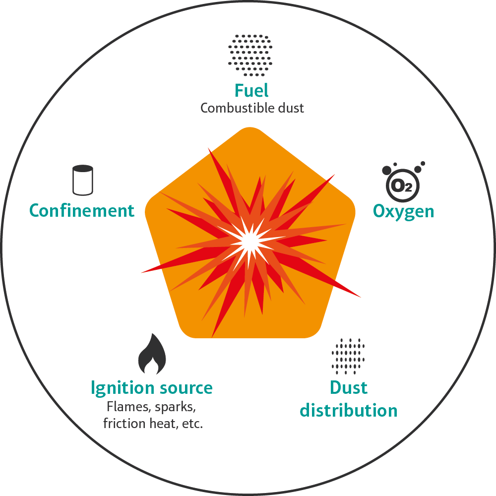
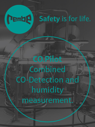
Explosion prevention concepts are designed to prevent a build-up of explosive dust or gas/air mixtures and/or ignition sources. The goal here is to reduce the probability of explosions occurring. Various options are available: dedusting and cleaning, inerting, earthing, vibration monitoring, camera systems for nozzle monitoring and the use of CO detection systems.

But even if all these precautions have been taken, reliable or complete explosion safety is often not guaranteed.

Explosion protection, by contrast, involves reducing the effects of an (inevitable) explosion and is the central, most frequently applied explosion safety concept.

Certified protective systems are used to safeguard employees, affected plant components and the entire environment. All available options for explosion protection are briefly described below.


Conventional venting via explosion vents

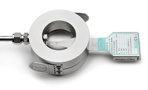
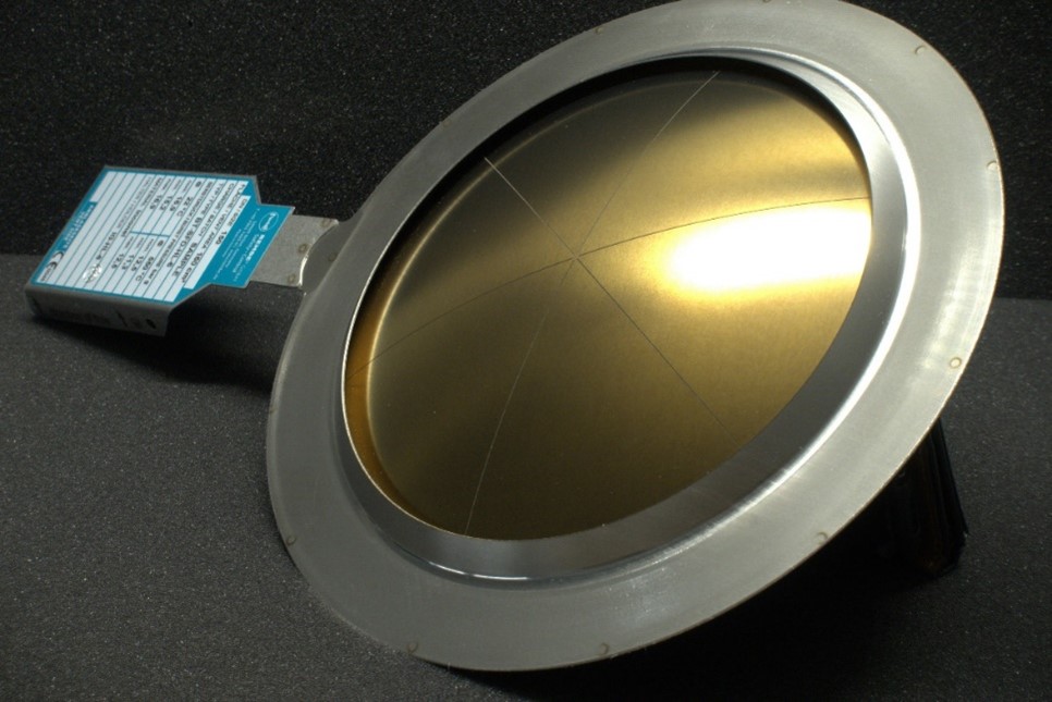
Explosion vents are often used in systems located outside buildings or for plant components mounted on an exterior wall. For example, dryers, silos, filters and elevators located outdoors are protected in this way. In the event of an explosion, the explosion vent protects the corresponding system by opening, thus dissipating the overpressure in the vessel and releasing the explosion outside to a safe area. Since virtually no two industrial processes are the same, various types of explosion vents are available, which differ in terms of their shape, material, temperature and pressure/vacuum resistance. Nowadays, even processes that are subject to strict hygiene requirements can be protected using explosion vents. For example, the EGV HYP hygienic explosion vent instantaneously protects critical systems such as spray dryers with or without wet cleaning, fluid bed dryers, filters and mixers, thus providing a cost-effective protection solution that ensures compliance with the requirements of hygienic design.

Screenshot_2022-07-22_113910.png


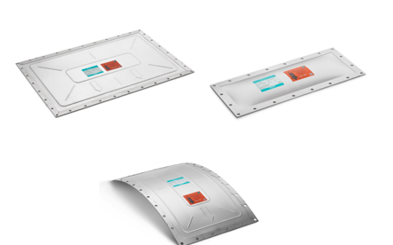
Fig. 1: Explosion vents differ in shape and structure depending on the application.


Flameless explosion venting for plants inside buildings

For plants located inside buildings, explosion vents are not suitable due to the lack of a sufficiently large safety area into which the escaping dust and flames can be directed. Since this represents an enormous safety risk for personnel and plant components alike, this problem is often solved by means of vent ducts, also called relief ducts. However, the latter often preclude a process-optimised plant design and are usually very expensive, since the pressure that the duct and the system must withstand increases in proportion to the distance from the explosion source. This cost increase is due to the fact that the vessels to be protected require increased compressive strength.

Flameless venting is an economical and effective solution. Different manufacturers use various technologies to ensure flameless venting.

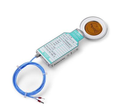
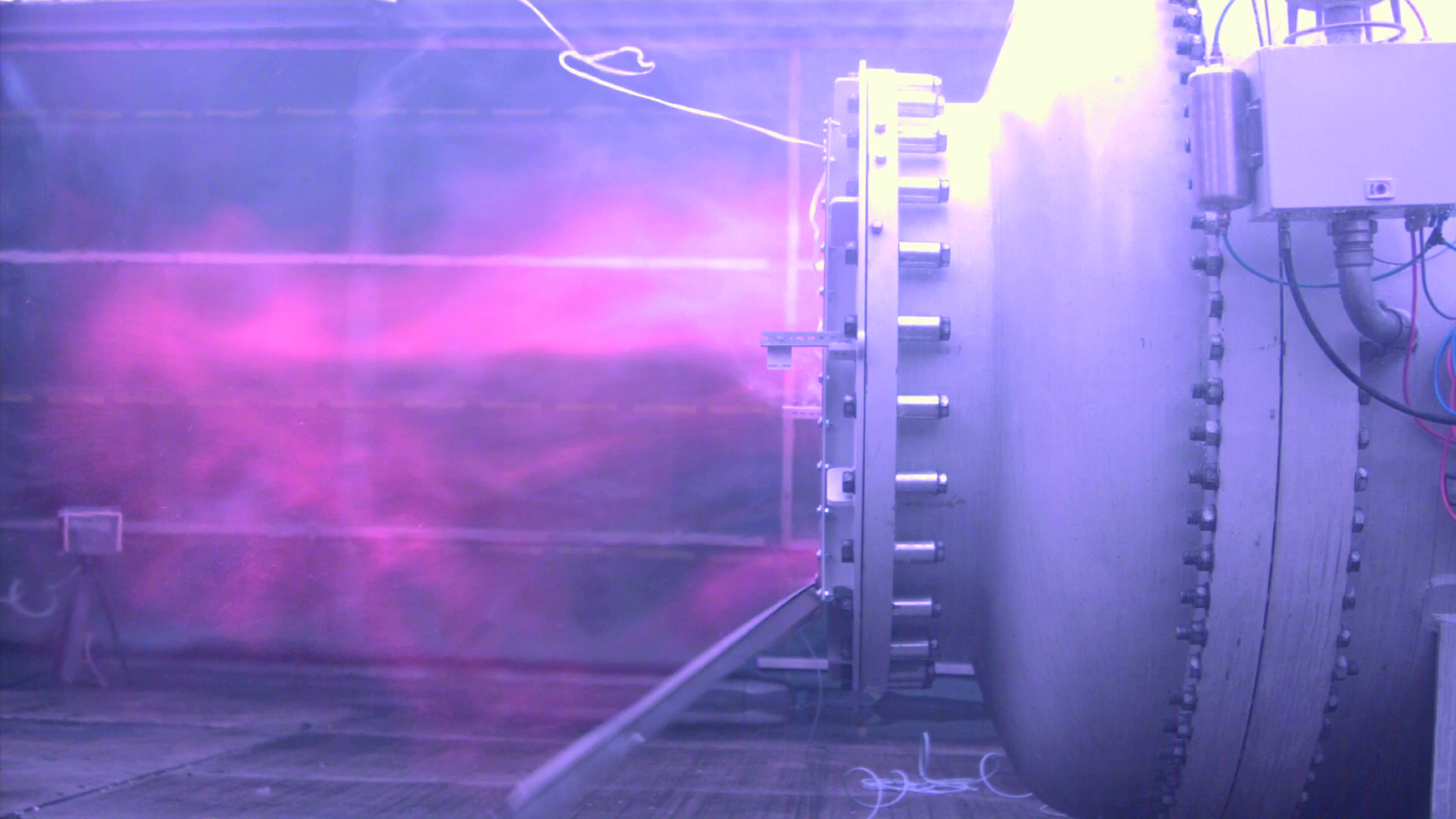
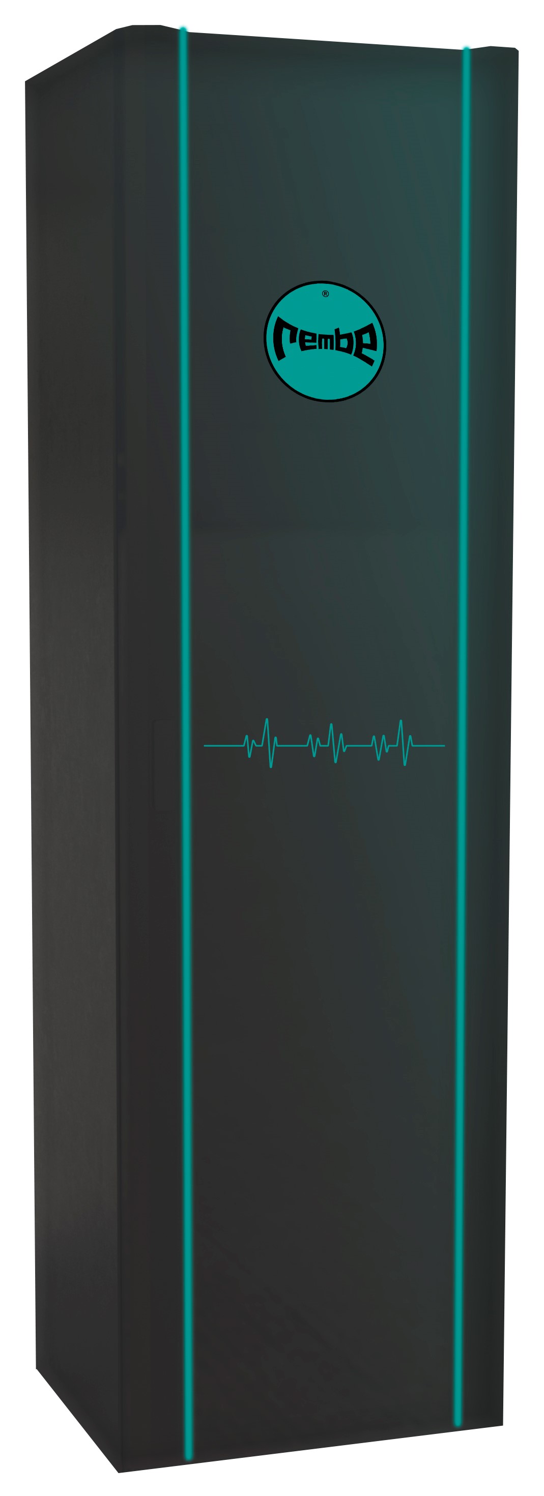
REMBE, the inventor of flameless venting, offers three different products: Q-Rohr, Q-Box and Q-Ball. The special stainless steel mesh filter inlet used in the products cools down flames efficiently so that no flames or pressure escape. The typical pressure increases and noise during an indoor explosion are reduced to a barely perceptible minimum, ensuring the protection of both man and machine. In addition to the special stainless steel mesh filter, Q-Ball, Q-Rohr and Q-Box consist of an explosion vent with integrated signalling, which informs the process control system about the burst of the explosion vent.

Picture2.png

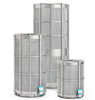
Fig. 2: Flameless venting Q-Rohr

Explosion isolation

In every production facility, individual plant components are interconnected by means of pipelines. The purpose of explosion isolation systems is to seal these pipelines in the event of an explosion to prevent the propagation of pressure and flames, thereby protecting the adjacent plant components. A distinction is made here between active and passive isolation systems.

Active systems use sensors or detectors to detect an explosion as it occurs. They register the rising pressure or flames as they form and activate the associated isolation device, e.g. a quench valve. Due to their structural design, passive isolation systems, which are ideal for dust applications, react purely mechanically to a build-up or loss of pressure. Explosion isolation flap valves are a popular example of such a solution. They are kept open during normal operation by means of the currents present in the pipeline. In the event of an explosion, the valve closes due to the expanding pressure front, effectively preventing the propagation of pressure and flames.


Explosion suppression

In addition to the methods already mentioned, explosion suppression is another aspect of explosion protection. In this case, the idea is to eliminate the explosion before it can fully form. This is made possible by detectors that use sensors to detect pressure or flames and immediately trigger the extinguishing agent canisters that are also installed in the system. The latter disperse a highly effective extinguishing agent within milliseconds and thus nip the explosion in the bud. If required, an explosion suppression system can also be used for explosion isolation.

The Q-Bic extinguishing barrier from REMBE was developed in strict compliance with the hygiene requirements for spray-drying plants. Thanks to the convex dirt protection cap, neither water nor dust deposits can accumulate on the Q-Bic. The blue-green QXP extinguishing powder prevents cross-contamination and the patented SJX nozzle ensures optimum application of the extinguishing powder. The Q-Bic is particularly suitable for large pipes attached to dryers and filters or complex shaft geometries such as conveyors and elevators.

Picture3.png

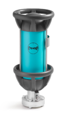
Fig. 3: REMBE extinguishing barrier Q-Bic


Protection of spray dryers and cyclones – a case study

The task is to protect a spray dryer and a connected cyclone; the product is discharged via the cyclone.

The technical data at a glance:

  • Drying temperature: 90˚C
  • Dust specifications:
    • organic dust St1
    • KSt value: 150 bar*m/s
    • Pmax: 8 bar
    • lower explosion limit: 255g/m3
    • strength of all system elements: tested Pdesign of min. 0.3 bar

A safety concept is required that incorporates as few explosion safety products as possible. This is a common requirement; however, it can only be met by considering the plant as a whole and taking all technical specifications, as well as the latest research findings, into account.

In the present case, explosion isolation of the spray dryer from the cyclone is not necessary. At first glance, this contradicts the statement made earlier that isolation is absolutely necessary to prevent an explosion from propagating. However, scientific evidence shows that decoupling can be dispensed with if a Pred of max. 0.3 bar is determined for the entire plant, since any hazardous pre-compression in the neighbouring equipment can then be ruled out.

Protection for the spray dryer

VDI guideline 2263, or more precisely Sheet 7.1, states that under the following circumstances a reduced volume can be assumed when calculating the necessary vent areas / protective systems:

1.         No integrated fluid bed

2.         No recirculation of fine dust into the head of the spray dryer

3.         The average dust concentration inside the spray dryer is lower than the lower explosion limit of the dust.

If these three conditions are met, as in the present case, either a reduced volume of 1/3 of the total volume or the volume of the cone can be assumed. The larger volume must be selected in each case.

For the spray dryer in question, 1/3 of the total volume, i.e. 19.85 m3, was selected.

Observance of VDI guideline 2263, Sheet 7.1. allows an additional reduction in addition to the volume, resulting in smaller required vent areas. If it can be assumed that, due to the process, the optimum dust concentration for an explosion will never be present, the protective systems can be designed with a reduced KSt value. Due to the nature of the process – the product is to be dried after all – it has been scientifically proven that a maximum concentration of 250 g/m³ cannot occur in the spray drying system.

The inclusion of the latest research results and current guidelines in the design thus leads to a reduction in the volume to be considered and the KSt value. This in turn allows the creation of a safety concept that is not only safe but also cost-effective. By comparison, without taking these reductions into account, the vent areas for the spray dryer to be protected would have been up to 340% larger. From the operator's point of view, this is over-engineering, because larger relief areas always mean greater effort to modify the respective plant components and, last but not least, higher acquisition costs.

The following table shows how the protection system for the spray dryer under consideration might look with and without the described design requirements:

Protective systems in use

Conventional design

Design according to the latest research findings

Explosion vents, free venting to outside areas*

4 x EGV HYP hygienic explosion vents (586x920mm) (with EHEDG approval)

1 x EGV HYP hygienic explosion vent (586x920mm) (with EHEDG approval)

Flameless explosion venting

5 x Q-Box 586x920 with EGV HYP hygienic explosion vent

2 x Q-Box 586x920 with EGV HYP hygienic explosion vent

Combination of vent ducts and explosion vents

5 x EGV HYP hygienic explosion vents (586x920mm) (with EHEDG approval)

+ duct cover

1 x EGV HYP hygienic explosion vent (586x920mm) (with EHEDG approval)

+ duct cover

Suppression

3 x extinguishing agent bottles (45 l)

2 x extinguishing agent bottles (45 l)

* Rather unusual in the industry, as the plants are typically located inside buildings and "free" explosion venting is therefore not possible.

For round vessels such as spray dryers, selected flameless explosion venting systems, e.g. the Q-Box, can be installed by means of an adapter flange. Since the entire plant is located inside a building and the operator wanted an explosion protection system with the lowest possible maintenance requirements, flameless venting was chosen in this example.


Protection for the cyclone

For the associated cyclone, the original safety characteristics of the dust in question must be taken into account. Cyclones are usually vented via the vortex finder, which must be included in the design as a vent duct. Therefore, it is also crucial to know the exact dimensions of this plant component. In this particular case, the cyclone is protected by a DN 800 Q-Rohr equipped with an ERO hygienic explosion vent. By ensuring that the smooth surface of the explosion vent faces the processing area, all hygiene requirements from production are met.

The product discharge area below the cyclone is equipped with an explosion-proof and flame-proof rotary valve.


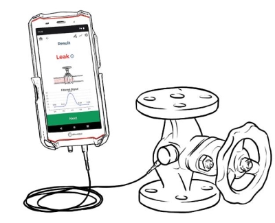
Risk of tampering with safety systems

Even the highest quality protective systems can only do their job if they are installed correctly and protected against tampering. The risk of tampering is an important issue, and also one that is sometimes ignored.

Recently, REMBE engineers have found indications of such deficiencies increasingly frequent during plant inspections:

For example, safety devices are disabled, electronic signalling and warning devices are bridged, mechanical elements are secured with too few fasteners and bolts. The reasons for this are complex and certainly not easy to understand.

The protective systems from renowned manufacturers such as REMBE are therefore designed from the ground up to ensure a high degree of in-built safety that is immune to tampering. For example, screw connections are replaced by non-detachable riveted connections; bolts are designed to be self-locking and captive.

This is particular essential for more complex components such as devices for flameless venting. These systems are typically installed indoors, but always in locations where free venting, e.g. via explosion vents, is not possible. However, if the part responsible for flameless venting fails or has any weak points, this could have devastating consequences for the surrounding area, which would be left defenceless against the flames and pressure of an explosion.

Picture4.png

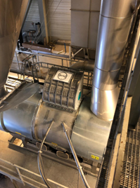
Fig. 4: REMBE Flameless venting on a fluidbed

www.rembe.de